Understanding industrial electrical schematics is crucial for engineers and technicians; these diagrams offer detailed insight into complex systems.
Learning to navigate PDF schematics, utilizing zoom and search features, enhances comprehension and troubleshooting capabilities within industrial settings.
What are Industrial Electrical Schematics?
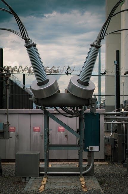
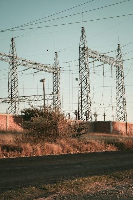
Industrial electrical schematics are detailed blueprints representing the components and connections within complex electrical systems found in manufacturing plants, power distribution networks, and control systems. Unlike simple household wiring diagrams, these schematics employ standardized symbols to illustrate devices like motors, transformers, switches, and protection devices – fuses and circuit breakers.
Essentially, they are high-level documentation providing engineers and technicians with a comprehensive overview of a circuit’s functionality. Reading these schematics requires understanding these symbols and how they interact. PDF formats are common for distribution, necessitating skills in navigating features like zoom, layers, and search functionality to efficiently interpret the diagrams. They aren’t meant to be immediately intuitive to a layman, but rather a precise language for electrical professionals.
Why Learn to Read Them?
Mastering industrial electrical schematics is paramount for effective troubleshooting, maintenance, and modification of electrical systems. The ability to decipher these diagrams minimizes downtime, enhances safety, and reduces costly errors. Understanding schematics allows technicians to quickly pinpoint faults, trace circuits, and implement repairs efficiently.
Furthermore, it’s essential for designing system upgrades or expansions. Being proficient in reading PDF schematics – utilizing features like zoom and search – streamlines the process of locating specific components or circuits within large, complex documents. It’s not just about identifying symbols; it’s about understanding the logical flow of electricity and the intended operation of the system. This skill is vital for career advancement in the electrical field.
Basic Electrical Symbols
Recognizing standard electrical symbols – for power sources, switches, motors, and protection devices – is foundational.
These icons are the building blocks for interpreting any industrial schematic PDF.
Power Sources & Grounding Symbols
Identifying power source symbols is paramount when reading industrial electrical schematics in PDF format. A common symbol represents DC power – a series of positive and negative lines – while AC power is depicted as a sine wave. Understanding voltage and current ratings associated with these symbols is vital.
Grounding symbols, often resembling stacked horizontal lines narrowing downwards, indicate the connection to earth, ensuring safety and proper circuit function. Different grounding methods exist, and the schematic will illustrate the specific configuration. Recognizing these symbols within a PDF schematic allows for tracing current flow and identifying potential fault paths. Correct interpretation of these symbols is essential for safe and effective troubleshooting.
Furthermore, variations in these symbols can denote different types of power sources or grounding schemes, so referencing a symbol key within the PDF document is always recommended.
Switch & Relay Symbols
Decoding switch and relay symbols within an industrial electrical schematic PDF is fundamental. A simple switch is often represented by an open or closed contact, indicating its on/off state. Multiple switches can be shown in series or parallel, influencing circuit behavior.
Relay symbols are more complex, typically featuring a coil and contacts. The coil represents the electromagnetic component activated by a control signal, while the contacts illustrate the circuit connections made or broken. Understanding normally open (NO) and normally closed (NC) contacts is crucial for interpreting relay functionality.
When reviewing a PDF schematic, pay attention to contact numbering and coil voltage ratings. These details are essential for tracing control circuits and diagnosing relay-related issues. Proper identification of these symbols enables effective troubleshooting and maintenance of industrial systems.
Motor & Transformer Symbols
Identifying motor and transformer symbols within an industrial electrical schematic PDF is vital for understanding power distribution. Motors are commonly depicted as circles or rectangles with windings, indicating the stator and rotor. Horsepower (HP) and voltage ratings are often noted nearby for quick reference.
Transformer symbols typically feature two windings – primary and secondary – represented by coiled lines around an iron core. The turns ratio is sometimes indicated, revealing the voltage transformation. Understanding these symbols allows tracing power flow and identifying potential overload conditions.
When examining a PDF schematic, note the motor starter and overload protection associated with each motor. For transformers, pay attention to the connection type (delta or wye) and tap settings. Accurate interpretation of these symbols is key to efficient system analysis.
Protection Devices (Fuses, Circuit Breakers)
Recognizing fuse and circuit breaker symbols within an industrial electrical schematic PDF is paramount for safety and troubleshooting. Fuses are typically represented by a broken line within a capsule, often with amperage ratings clearly marked. Understanding these ratings is crucial for identifying potential overload scenarios.
Circuit breakers are shown as hinged levers or toggle switches, indicating their ability to interrupt current flow. Their trip curves and amperage ratings are vital for assessing system protection. When reviewing a PDF, locate the coordination study to understand how these devices interact.
Pay close attention to the placement of protection devices in relation to motors and transformers. Proper coordination ensures selective tripping, minimizing downtime. Accurate interpretation of these symbols is essential for maintaining a safe and reliable industrial electrical system.
Understanding Schematic Diagram Types
Different diagram types—point-to-point, wiring, and ladder—exist within industrial schematics PDFs. Recognizing these variations is key to interpreting circuit functionality and flow effectively.
Point-to-Point Schematics

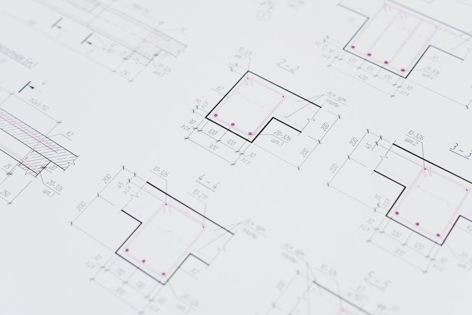
Point-to-point schematics, often found within older PDF documentation, illustrate each component and its direct connections. Unlike more abstract representations, these schematics prioritize a literal depiction of wiring.
When reading a PDF containing a point-to-point schematic, focus on tracing each wire’s path from terminal to terminal. This method is beneficial for understanding the physical layout, but can become cluttered in complex systems.
Pay close attention to component placement, as it often reflects the actual physical arrangement. Successfully interpreting these schematics requires patience and a systematic approach to following each connection. Zooming within the PDF viewer is essential for clarity, and understanding the legend is paramount.
Wiring Diagrams vs. Schematics
Wiring diagrams, frequently encountered in PDF manuals, differ significantly from schematics. While schematics prioritize logical function, wiring diagrams emphasize physical layout and component locations. This distinction is crucial when reading industrial electrical documentation in PDF format.
Wiring diagrams show the actual wiring routes and connections, often resembling a map of the physical installation. Schematics, conversely, use abstract symbols to represent components and their relationships. When analyzing a PDF, identify which type of diagram you’re viewing.
Understanding this difference allows for efficient troubleshooting and maintenance. Utilize the PDF’s search function to locate specific components and trace their wiring paths. Recognizing the diagram type is the first step to effective interpretation.
Ladder Diagrams (Ladder Logic)
Ladder diagrams, prevalent in PDF documentation for Programmable Logic Controllers (PLCs), represent control systems using a graphical language resembling relay logic. These diagrams, often found within industrial electrical schematics in PDF format, depict circuits as “rungs” of a ladder.
Each rung represents a control circuit, with power flowing from left to right. Understanding these diagrams requires recognizing common symbols for contacts, coils, and timers. When reviewing a PDF, focus on the logic flow within each rung to determine the control sequence.
Mastering ladder logic is essential for troubleshooting and modifying PLC-controlled systems. Utilize the PDF’s zoom function for detailed examination and search capabilities to locate specific rungs or components.
Key Elements of a Schematic
Schematics utilize lines, component IDs, and terminal blocks for clarity. PDF navigation tools help decipher connections and understand the flow of electricity within systems.
Lines and Their Meaning
Understanding line types is fundamental when reading industrial electrical schematics, especially in PDF format. Solid lines typically represent physical conductors, showing the actual wiring. Broken or dashed lines often indicate pilot circuits or control signals, distinct from power paths. A dotted line might represent a wireless connection or a desired, but not yet implemented, change.
When examining a PDF schematic, pay attention to line weights; thicker lines can denote more significant connections. Lines crossing without a dot usually signify no electrical connection, while a dot indicates a junction where wires are joined. Properly interpreting these visual cues within the PDF document is essential for tracing circuits and diagnosing issues effectively. Consistent line usage ensures clarity and reduces ambiguity.
Component Identification & Numbering
Component identification within industrial electrical schematics, particularly in PDF documents, relies heavily on standardized numbering systems. Each component – motors, relays, sensors – receives a unique identifier, often a combination of letters and numbers. These designations are crucial for cross-referencing with equipment lists and manufacturer documentation, easily accessible when viewing the PDF.
PDF schematics frequently include a bill of materials (BOM) or a component table that lists these identifiers alongside detailed specifications. Understanding the numbering scheme allows for quick location of components within the circuit. Consistent numbering practices, clearly visible in the PDF, minimize confusion and streamline troubleshooting. Proper identification is paramount for accurate maintenance and repair procedures.
Terminal Blocks and Connections

Terminal blocks are essential components in industrial electrical systems, and their representation in schematics, especially PDF versions, requires careful attention. These blocks serve as connection points for multiple wires, simplifying wiring and maintenance. PDF schematics clearly depict terminal block designations (e.g., TB1, TB2) and the associated terminal numbers.
Understanding how wires connect to these terminals is vital. Schematics illustrate connections using lines and symbols, indicating wire numbers or labels. When reviewing a PDF, zoom functionality helps discern these details. Proper interpretation of terminal connections ensures correct wiring during installation or repair. PDF documents often include terminal assignment charts, providing a comprehensive overview of each terminal’s function and connected components.
Reading a PDF Schematic
PDF schematics require utilizing features like zoom, layers, and search functions for effective navigation. Revision control within PDFs is also crucial for understanding updates.
Navigating PDF Features (Zoom, Layers)
Effectively reading industrial electrical schematics in PDF format hinges on mastering the document’s features. Zoom functionality is paramount; intricate diagrams demand the ability to magnify sections for detailed inspection of symbols and connections. Utilize the zoom tool to focus on specific components or areas of interest, ensuring clarity and minimizing errors.
Furthermore, many complex schematics are organized using layers. These layers allow you to toggle the visibility of different circuit sections, simplifying the diagram and focusing on specific aspects. Learning to manage layers prevents visual clutter and aids in tracing signal paths. Explore the layers panel within your PDF viewer to isolate and analyze individual parts of the electrical system. Proper use of zoom and layers significantly improves readability and comprehension.
Using Search Functionality
Efficiently locating specific components or reference designators within a complex industrial electrical schematic PDF relies heavily on the search function. Instead of manually scanning lengthy diagrams, utilize the search tool (typically Ctrl+F) to quickly find instances of component IDs, wire numbers, or specific symbol names.
Remember that search functionality is case-sensitive in some PDF viewers, so experiment with different capitalization variations if your initial search yields no results. Searching for unique identifiers, like a specific fuse number or motor designation, is far more effective than broad terms. Mastering this skill dramatically reduces troubleshooting time and enhances your ability to understand the schematic’s overall structure. It’s a vital tool for navigating large and detailed electrical drawings.

Understanding Revision Control in PDFs
Industrial electrical schematics frequently undergo revisions, making version control critical when working with PDF documents. Look for revision blocks or tables within the PDF, typically located in the title block, detailing the date, revision number, and a brief description of the changes made.
Understanding this history prevents using outdated information, potentially leading to errors or safety hazards. Some PDF viewers display revision information in a sidebar or properties panel. Always confirm you’re referencing the latest approved revision before making any decisions based on the schematic. Ignoring revision control can result in misdiagnosis and incorrect repairs, emphasizing its importance in maintaining system integrity and safety.
Common Schematic Errors & Troubleshooting
Identifying errors like missing information or incorrect symbols is vital. Discrepancies require careful interpretation and cross-referencing with other documentation for accurate troubleshooting.
Identifying Missing Information
When reviewing industrial electrical schematics, particularly in PDF format, a critical troubleshooting step involves identifying missing information. Often, schematics may lack crucial details like wire numbers, component values, or specific terminal block designations. This absence can significantly hinder understanding and effective fault diagnosis.
Carefully examine the diagram for incomplete connections or ambiguous labeling. Cross-reference the schematic with associated documentation, such as equipment manuals or parts lists, to verify the presence of all necessary data. Pay close attention to power supplies and grounding connections, as omissions in these areas can lead to safety hazards or system malfunctions.
Utilize the PDF’s search functionality to locate specific components or parameters; their absence from the schematic may indicate missing information. A well-maintained schematic should provide a comprehensive representation of the electrical system, and any gaps should be addressed before proceeding with maintenance or repair.
Recognizing Incorrect Symbol Usage

Accurate interpretation of industrial electrical schematics, especially in PDF documents, hinges on correctly identifying electrical symbols. Incorrect symbol usage is a common error that can lead to misdiagnosis and potentially dangerous repairs. Familiarity with industry standards like IEC or ANSI is vital for recognizing deviations.
Scrutinize each symbol to ensure it accurately represents the intended component or function. For example, a mislabeled relay or a fuse depicted with the wrong symbol can cause significant confusion. Pay attention to subtle differences in symbol variations, as these often indicate specific characteristics.
When encountering unfamiliar symbols, consult online symbol libraries or reference guides to confirm their meaning. A PDF’s search function can help locate similar symbols within the document for comparison. Consistent and correct symbol usage is paramount for a reliable and understandable schematic.
Interpreting Discrepancies
When reviewing industrial electrical schematics in PDF format, discrepancies can arise between the diagram and the actual physical system. These inconsistencies require careful interpretation to avoid errors. Common issues include mismatched component numbering, incorrect wiring connections, or outdated revision levels.
Utilize the PDF’s search functionality to cross-reference component IDs and verify their corresponding locations on the schematic. Compare the diagram with physical equipment, noting any differences in wiring or component types. Document all discrepancies and consult with experienced personnel for clarification.
Revision control within the PDF is crucial; ensure you’re viewing the latest version. Discrepancies may stem from outdated schematics. A thorough understanding of the system’s operation and a systematic approach to comparison are essential for accurate interpretation.
Resources and Guides
Industry standards like IEC and ANSI provide frameworks for schematic interpretation. Online symbol libraries and recommended learning materials aid in mastering PDF schematics.

Industry Standards (IEC, ANSI)

Adhering to established industry standards is paramount when interpreting industrial electrical schematics, especially those found in PDF format. The International Electrotechnical Commission (IEC) develops and publishes international standards for all electrical, electronic and related technologies. These standards ensure consistency and clarity in schematic representation globally.
Similarly, the American National Standards Institute (ANSI) plays a vital role in the United States, approving American National Standards that impact schematic design and interpretation. Understanding these standards – particularly those relating to symbols, line types, and component identification – is crucial for accurately reading and troubleshooting complex electrical systems documented in PDF schematics.
Familiarity with these standards minimizes ambiguity and promotes safe and efficient operation of industrial equipment. Resources detailing these standards are available through official IEC and ANSI websites, offering comprehensive guides for professionals.
Online Symbol Libraries
Navigating industrial electrical schematics in PDF format often requires quick reference to symbol meanings. Fortunately, numerous online symbol libraries are readily available to assist in decoding these diagrams. These digital resources provide comprehensive collections of electrical and electronic symbols, often searchable by keyword or category.
Websites like Electrical Symbols Library and others offer extensive databases, allowing users to quickly identify unfamiliar components and their corresponding representations. These libraries are invaluable when encountering diverse schematics from various manufacturers or regions.
Utilizing these online tools streamlines the interpretation process, especially when dealing with complex PDF documents. Many libraries also include detailed explanations of each symbol’s function and application, enhancing understanding and troubleshooting capabilities.
Recommended Learning Materials
Mastering industrial electrical schematics, particularly within PDF documents, benefits greatly from structured learning resources. Several books and online courses cater specifically to this skill. “Electrical Motor Controls for Integrated Systems” provides a solid foundation in schematic interpretation and motor control circuits.
Online platforms like Udemy and Coursera offer courses focused on electrical schematics and ladder logic, often including practical exercises. The IET (Institution of Engineering and Technology) publishes guides on units and symbols for electrical and electronic engineering, offering standardized references.
Supplementing these resources with manufacturer-specific documentation and training materials is crucial for understanding unique schematics. Regularly practicing with real-world PDF schematics will solidify comprehension and build confidence in interpreting complex diagrams.